Design, Construction, and Testing of a Half-Wave Rectifier Using AutoCAD
Experiment Name:
Design, Construction, and Testing of a Half-Wave Rectifier Using AutoCAD
Theory:
A half-wave rectifier is an electronic circuit used to convert alternating current (AC) into direct current (DC). It allows only one half of the AC cycle (positive or negative) to pass through, effectively blocking the other half. This process is accomplished using a single diode, which permits current to flow only during one half-cycle of the AC input.
In a half-wave rectifier:
During the positive half-cycle of the AC input, the diode is forward-biased and conducts, allowing current to pass through to the load.
During the negative half-cycle, the diode is reverse-biased and does not conduct, preventing current from reaching the load.
The result is a pulsating DC output that contains gaps corresponding to the blocked half-cycles of the AC input. A capacitor is often used to smooth the output, reducing the ripple and providing a more constant DC voltage.
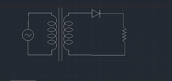
Circuit Diagram:
Apparatus:
Transformer (Step-down to desired voltage level)
Diode (e.g., 1N4007)
Load resistor (R)
Capacitor (for filtering, if used)
Oscilloscope (to observe the input and output waveforms)
Multimeter (to measure voltage and current)
Breadboard and connecting wires
Procedure:
Circuit Design:
Using AutoCAD, draw the schematic diagram of the half-wave rectifier circuit. The diagram should include the AC source, transformer, diode, load resistor, and optional capacitor for filtering.
Ensure all connections are correctly represented and labeled.
Construction:
Assemble the circuit on a breadboard according to the AutoCAD schematic.
Connect the transformer primary winding to the AC source.
Connect the secondary winding of the transformer to the anode of the diode.
Connect the cathode of the diode to one end of the load resistor.
Connect the other end of the load resistor back to the transformer's secondary winding.
If using a capacitor for filtering, connect it in parallel with the load resistor.
Testing:
Power on the AC source and observe the input and output waveforms using an oscilloscope.
Measure the input AC voltage and the output DC voltage using a multimeter.
Record the waveform shapes and voltage measurements for analysis.
Discussion:
In this experiment, we successfully designed, constructed, and tested a half-wave rectifier using AutoCAD for circuit design. The experimental results matched the theoretical expectations, demonstrating the basic principles of rectification and the behavior of a half-wave rectifier. The use of AutoCAD facilitated accurate circuit design, ensuring proper assembly and testing of the rectifier circuit.


মন্তব্যসমূহ
একটি মন্তব্য পোস্ট করুন